Introduction to Engineering Drawing for Technicians Unit
It is important that when a product has been designed it is manufactured correctly and to specification. To achieve this, it is crucial that the people making the product in a workshop are provided with well-presented engineering drawings, produced to international standards and conventions. Positively, this avoids errors of interpretation that can lead to the scrapping of expensive parts. As such, the Engineering Drawing for Technicians unit covers these aspects.
Additionally, an understanding of how graphical methods can be used to communicate information about engineering products. Moreover, it is an important step for anyone thinking of taking up a career in engineering. Therefore, this Engineering Drawing for Technicians unit gives learners an introduction to the principles of technical drawings. Additionally, learning their applications using hand drawing and computer-aided design (CAD) techniques.
What’s covered in the Engineering Drawing for Technicians Unit?
What’s more, learners will start by carrying out freehand sketching of simple engineering products using pictorial methods that generate three-dimensional (3D) images. A range of standard components, such as fixing devices, will be sketched together with other solid and hollow items. Learners are then introduced to a more formalised drawing technique that conforms to British Standards and will put this into practice through a number of drawing exercises. A consistent presentation style will be used as learners draw single part components and simple engineering assemblies.
These drawings will contain all the information needed to manufacture or assemble the product, including information such as dimensions, manufacturing notes and
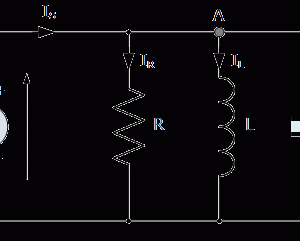
parts lists. The use of conventions to represent standard items will be investigated, such as screw threads and springs in mechanical type drawings or circuit symbols
such as solenoids and resistors in electrical/electronic type drawings.
Having learned the principles of engineering drawing, learners will then move on to using a two-dimensional (2D) CAD system for the production of drawings using basic set-up, drawing and editing commands. The first task is to produce a drawing template which can be saved to file, as this reinforces the concept of standardisation and consistency of presentation. This is followed by drawing exercises of single-part components, a simple multi-part assembly and circuit diagrams. For further information, please visit here.
Learning outcomes
On completion of this unit a learner should:
- Firstly, sketch engineering components
- Secondly, interpret engineering drawings that comply with drawing standards
- Thirdly, be able to produce engineering drawings
- Lastly, produce engineering drawings using a computer-aided design (CAD) system.
Where can I contact you if I have questions?
If you have any queries regarding the post above, please contact us here.


Reviews
There are no reviews yet.